Military DT-590A/PDR-56 “x-ray” probes are widely available in the surplus market. They were meant to be used with the military Radiac Set AN/PDR-56, which is a portable scintillation-type instrument used for detection of plutonium-239 contamination. In addition to emitting 5.1 MeV alpha particles, Plutonium-239 also emits gamma rays in the energy range of 14 to 21 keV. Because these gamma rays are more penetrating than the alpha particles, they travel further in matter and air and can be detected at longer distances from the ground. The probe uses a CaF2(Eu) scintillator/photomultiplier combination to detect these 14-21 keV gammas from Pu-239. The discriminator inside the probe is factory-tuned to detect only pulses from the Pu-239 gamma rays. Hopefully you don’t have plutonium contamination in your basement, so you can set the discriminator window wide open to make the probe sensitive to a much wider range of gamma energies. In addition, you can replace the CaF2(Eu) crystal by a NaI(Tl) scintillation crystal assembly. This will turn the instrument into a general-purpose gamma radiation detector that will outperform virtually any handheld Geiger counter in the detection of 100keV to 1.3MeV photons.
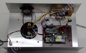
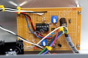
 This pdf file shows the schematic diagram of my home-built circuit to drive the PDR-56 probe. A JKL BXA-12579 inverter commonly used to drive cold-cathode fluorescent lamps is used as the high-voltage power supply. The BXA-12579 produces 1,500 VACRMS for a 12 VDC input. The AC output is tapped straight from the transformer’s secondary and rectified by D1, a high-voltage diode rated at 20 kV and 0.5 A. The rectified signal is filtered by C1, R1 and C2. -950 VDC for operation of the photomultiplier tube inside the PFR-56 probe are regulated by a series of Zener diodes (D2 – D9). -9 V are generated by an isolated DKE 10A-05 DC/DC converter, and +3.8 V are derived from the 12VDC input by a 3-pin 5 V linear regulator (U1) with its output voltage dropped by 2 series diodes (D11 and D12).

 The signal input circuit is based directly on the military DT-590A/PDR-56 radiac meter as described in US Army Technical Manual TM 11-6665-245-34. In this part of the circuit, Q1, Q2 and Q3 form a discriminator and buffer-inverter circuit that determines the level of incoming pulses which are measured and provides a positive going pulse for use by U2. Prior to any signal (positive pulse from the buffer inverter circuit Q3), the inputs to NOR gate U2A are both low, the output is high and transistor Q4 is conducting. A positive going pulse from Q3 starts the circuit into operation. When pin 1, U2A, goes high, its output goes low. The voltage change is coupled directly to the base of Q4 through timing capacitor C10. Q4 is then cut off and its collector goes high holding the output of U2A low. This condition holds until timing capacitor C10 discharges through resistor R10 enough to allow Q4 to turn on, causing pin 2 of U2A to revert to a low condition. This action results in pin 3, U2A, first going low as the result of the inverter-buffer input pulse and then staying low until the timing capacitor discharges forming a negative going pulse on the inputs of U2B through U2D. Outputs from inverters U2B and U2C are tied together and connected to a piezo speaker to produce a “click” for each detection by the probe. In addition, the output of U2D can be routed to a counter, small audio amplifier or other instrument.

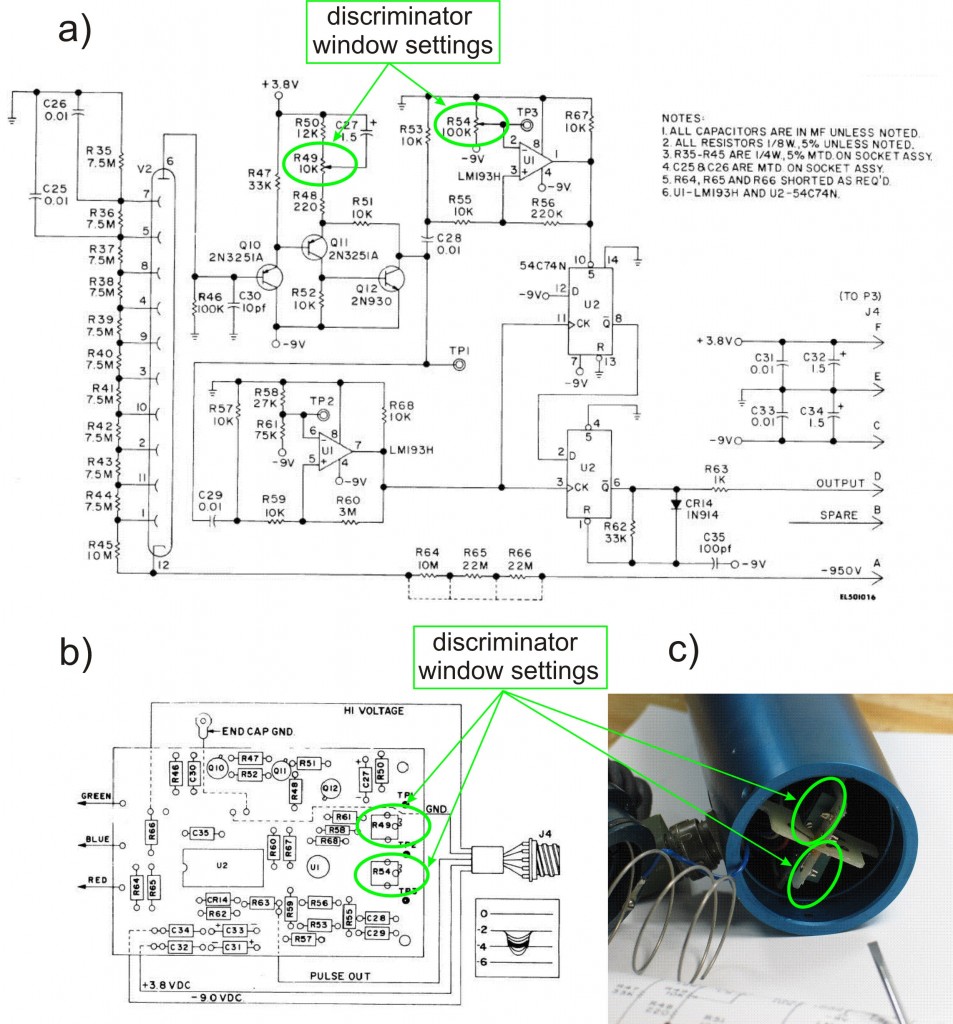
The circuit inside the probe is built as a single-channel counter, and is factory-tuned to detect only scintillation pulses from the Pu-239 gamma rays. Thus, you should open the single-channel window all the way to make the probe sensitive to a much wider range of gamma energies. The following picture shows the trimmers inside the probe that need to be re-adjusted:

