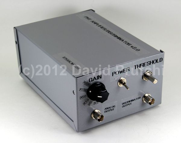
Figure 34 in the book shows the schematic diagram for the photomultiplier tube (PMT) signal processing circuit that amplifies the narrow pulses detected by the PMT probe. The discriminator stage removes small pulses produced by thermal noise in the tube. A pulse stretcher outputs pulses that can be heard on a speaker. In addition, the analog output is suitable for use with a sound-card-based multichannel pulse-height analyzer (MCA).
We are posting this set of pictures to help you build your own unit. The top-left inset shows a small circuit board containing op-amp U1, which is configured as an inverting charge-sensitive amplifier. This amplifier is placed right next to the input connector.
The positive-going pulses coming from this charge-sensitive preamplifier are turned into a Gaussian pulse by first differentiating (high-pass filtering) and then integrating (low-pass filtering) them by the circuits built around U2A and U2B. Trimmer R23 is used for pole cancellation to yield as clean a Gaussian pulse as possible through this simple configuration.
Pulses are further amplified by variable-gain stages. A comparator is used to convert pulses over a preset threshold into inverse-logic digital pulses that indicate a photon strikes. This discriminator stage gets rid of small-amplitude pulses caused by thermal noise in the PMT. Lastly, the pulses are stretched by a one-shot to provide an audible “click” through the piezo speaker. A buffer amplifier is also available to output the amplifier’s analog signal to an oscilloscope or to a multichannel analyzer. The complete circuit is power by two 9V batteries.

